1Institute of Structural Mechanics, Faculty of Civil Engineering, Brno University of Technology, Veveří 331/95, 602 00 Brno, Czech Republic
akitnarf@centrum.cz, bkersner.z@fce.vutbr.cz, cvesely.v1@fce.vutbr.cz, droutil.l@fce.vutbr.cz
Keywords: Impact, Fracture, Fragmentation, Fractal, Dynamic Simulation
Abstract. The paper is focussed on numerical simulations of the fracture of a quasi-brittle specimen due to its impact onto a fixed rigid elastic plate. The failure of the specimen after the impact is modelled in two ways based on the physical discretization of continuum: via physical discrete elements and pseudo-particles. Advantages and drawbacks of both used methods are discussed. The size distribution of the fragments of the broken specimen resulting from physical discrete element model simulation follows a power law, which indicates the ability of the numerical model to identify the fractal nature of the fracture. The pseudo-particle model, on the other side, can successfully predict the kinematics of the fragments of the specimen under impact failure.
Introduction
The paper deals with the results of numerical simulations of fracture in a ball-shaped specimen made of a selected building material impacting a fixed solid elastic plate. After the impact of the specimen onto the plate a fragmentation occurs due to fracture. It will be shown in this paper that the distribution of the fragments follows a power function indicating the fractal character of the fracture (Buchanan 2000, Odershede et al 1993).
The specimen is modelled two-dimensionally in two ways: via physical discrete elements and pseudo-particles. The material of the specimen assumed in the study can be seen as quasi-brittle, which is adequate e.g. to a fine cement-based composite or a building ceramics and clay wares. Nevertheless, this type of analysis can be technically performed with some modifications regarding the constitutive model definition on brittle materials too. In other words, the presented numerical simulations performed with specimens made of quasi-brittle building materials can be regarded as a special case of a general material failure dynamic analysis.
Presented results shows capability of described numerical models to simulate self-organized criticality in fragmenting. This behaviour as well as the fractality of fracture surface plays an important role in understanding of the general nature of fracture phenomena but in the field of numerical modelling it is frequently suppressed due to required simplifications or ignorance.
The authors of the paper are interested in the field of complex modelling of fracture of advanced building materials. The outline of that interest represents the most effective use yet of infrequently-used methods of complex material damage and failure modelling to study structural behaviour of various sorts of building materials which can exhibit a quasi-brittle behaviour in a rather broad range of its form transiting from nearly brittle behaviour of e.g. building ceramics to almost ductile behaviour of e.g. fibre-reinforced resin-matrix composites. Particular attention is paid to silicate-based composites, which are unquestionably among the most advanced materials in the field of construction and construction elements. Key members of this category include High Performance Concrete, cement composites of ultrahigh strength on the basis of ultrafine reactive ingredients (Reactive Powder Concrete) etc. One of the most actual areas of basic research of progressive building materials is apparently the fracture behaviour as well, because these materials are used for building structures or structural members which failure is typically linked with initiation and propagation of cracks.
Motivation
Advanced building materials in question are usually characterized by evaluation of their basic fracture-mechanical parameters which are determined using results of quasi-static fracture experiments. These parameters can be then used for a structural materials classification or their mutual comparison as a measure of the material resistance against the failure propagation or they can also serve as inputs for particular material models within computational codes developed for numerical simulation (prediction, assessment) of the structural response.
Fracture features of these quasi-brittle materials is studied from many viewpoints – see e.g. (Karihaloo 1995, Bažant and Planas 1998, Shah et al 1995, van Mier 1997). Fracture surfaces of these composites and also crack patterns are considered as irregular objects – natural fractals. The beginning of development of fractal characterization of irregularity of these objects is related to work of e.g. Mandelbrot (1982). Many authors deal with fractal characterization of fracture surfaces of concrete from the point of view of fractal dimension determination and also its correlation to others materials parameters, scaling aspects, etc. (e.g. Saouma et al. 1990, Brandt and Prokopski 1993, Bažant 1995, Carpinteri et al. 1999, Carpinteri and Invernizzi 2001, Mechtcherine and Muller 2001).
However, the motivation of this research is to investigate whether the studied numerical models (developed for the modelling of fracture processes, observed e.g. during the fracture experiments) can embody the so-called self-organized criticality during the fragmentation. This criticality is demonstrated by the power law of fragment size (volume) distribution arisen from the failure caused for example by impact of the specimen onto a fixed stiff elastic board. Presented research was inspired by experiments made by Odershede et al. (1993) which were focused on distributions of fragments due to fracture of objects made of gypsum, soap, stearic paraffin, and frozen potato. These materials generally cover wide area of different types of structural materials, both the brittle and the quasi-brittle ones. The power law characterizing the observed fragmentation is presented more precisely by the function (histogram) of the fragments’ frequency in classes sorting the fragments set according to their weight.
Numerical models
The used numerical models – assembled from physical discrete elements or pseudo-particles – are based on physical discretization of the specimen’s volume. Under the term physical discretization a representation of the “continuum” of the specimen by real discrete physical objects is meant (i.e. objects which can be really manufactured). These objects are supposed to create the geometrical model of the problem.
Both models are dynamic, in both models the modelled continuum is replaced by mass points as objects with state variables. However, the models differ in their representation of the interaction between the mass points and in the type of the interaction function.
A mass point in the physical discrete element model interacts only with neighbouring mass points to whose it is connected by a translational springs; see Fig. 1 on the left. In the pseudo-particle model a single mass point interacts with every other mass point in its neighbourhood defined by a particular radius; see Fig. 1 on the right.
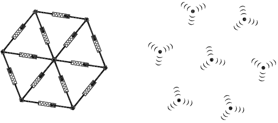
Fig. 1: Schemes of used models with indication of its basic elements and their mutual interaction: physical discrete elements (left) and pseudo-particles (right)
The interaction function of the translational spring in the physical discrete element model (used in the numerical simulations presented in the paper) corresponds with a constitutive model which is common in the field of quasi-brittle material failure modelling (see e.g. Karihaloo 1995, Bažant and Planas 1998, Shah et al 1995, van Mier 1997). The ascending linear parts in both tension and compression zone correspond with the linear elastic behaviour. However, the force–displacement dependence has two critical points: one in the compression zone and one in the tension zone, see Fig. 2. In the compression zone, the interaction force F remains constant after reaching the critical displacement uflat; in the tension zone, the ascending linear branch of the F–u dependence is followed by the descending linear part after reaching the critical displacement ucrit and ends at the value F = 0 for the displacement uzero. The unloading on the descending branch is assumed to be parallel to the linear elastic part.
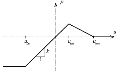
Fig. 2: The interaction function used in the simulations (F is interaction force and u is displacement from the equilibrium point)
The pseudo-particle model employs the same interaction function but the unloading is assumed to be “elastic”, i.e. without remaining inelastic displacements (damage) after peak of the F–u diagram.
Let us note that the intended range of the brittleness of the modelled material can be adjusted by the slope of the descending branch in the tensile region – from the immediate drop to zero corresponding to ideally brittle materials to even a long rising (hardening) branch followed by a steep descent which is characteristic for e.g. fibre-reinforced composites.
Each branch of the interaction function can of course be modelled by a nonlinear function appropriate to any particular material – a non-linearity on the ascending branches as well as a multi-linear or exponential softening both in the tension and the compression zone. A simple tri-linear interaction function was used in the case presented in this paper as the goal of the simulations has a purely qualitative nature.
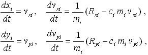
Both numerical models are then formulated in the same way using Newtonian classical mechanics as a nonlinear dynamical system – a system of ordinary differential equations:
| (1) |
where m is weight of the mass point, c is damping coefficient, t is time, xi and yi are mass point coordinates, vxi, vyi are mass point velocities, and Rxi, Ryi are components of the resultant of force interactions. This equation system is solved by basic numerical methods (Euler’s method, Runge-Kutta methods). Implementation of these models is freely available in the form of application FyDiK (Frantík 2007). A movie of this simulation is available on this website too.
Simulation results
The simulations were performed in the following manner: An initial velocity (tens of meters per second) in the direction perpendicular to the elastic wall was prescribed to a given representation of the specimen (a mesh created by the use of physical elements or pseudo-particles, respectively). Then, the calculation began, and it was stopped in the stage of the failure process, when the specimen was broken into fragments.
In the case of the physical discrete element model this moment corresponds to a stage when the fracture propagated through the entire specimen’s width. Fig. 3 shows three different physical discrete element meshes after fragmentation.
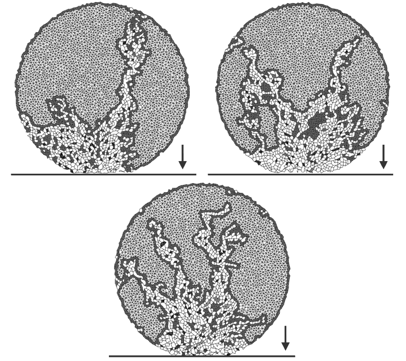
Fig. 3: Three different representations of the specimen after fragmentation, modelled by the physical discrete element method. The arrow shows the direction of impact of the round specimen with the solid elastic plate on the bottom
Because of considerable computational demands (see bellow) only one representation of the specimen was analyzed using the pseudo-particle model. Four stages of the simulated failure process during impact are depicted in Fig. 5.
Discussion of results
From Fig. 3 the complexity of the failure process is evident. The crack branching occurs accompanied by the formation of fragments of different sizes; some crack branches coalesce again during the simulation progress and the impacted part of the specimen is almost completely damaged. The resulting graph of the frequency of fragments formatted during failure versus the fragment size (represented as the number of lattices within the fragment) is plotted in Fig. 4. In the graph mean values from three simulations performed using the physical discrete element model are displayed.
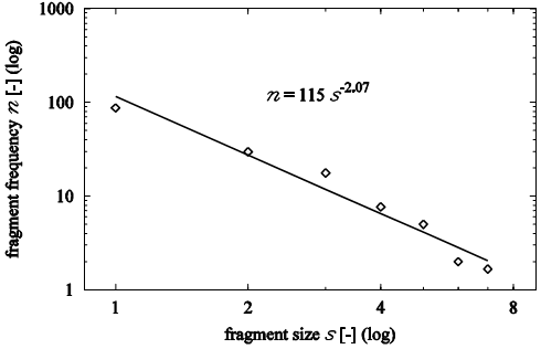
Fig. 4: Double-logarithmic plot of fragment frequency vs. fragment size for three model representations of the specimen (n – fragment frequency, s – fragment size, i.e. number of lattices within the fragment)
The power law founded by regression from the results of the physical discrete element model simulation (see Fig. 4) indicates that there is no typical size of fragments. This fact can be successfully explained by fractal geometry of fracture surface because exactly fractals are the objects without any typical scale (Mandelbrot 1982). The exponent of the power function represented in Fig. 4, however, does not have any direct relation with the fractal dimension of the fracture surfaces (generally noticeably higher than 2 for the modelled material type) or crack patterns (ditto > 1).
Nevertheless, the simulations also showed that the model is not able to simulate the impact failure process accurately in the stages just after fragmentation. Expected explosion of fragments does not occur. Under the term explosion a phenomenon is meant here when some fragments achieve high velocity (depending on the impact velocity) whereas its vector is nearly parallel to the elastic plate. This drawback is caused by the fact that one material point influences only the closest neighbouring points to which it is connected. These connections, however, practically vanish right away after the impact. Therefore, no “impact wedge” (a wedge-shaped part of the specimen near the area of contact with the elastic plate) – which is assumed to be the main cause of the explosion – is formed.
This disadvantage can be eliminated by the pseudo-particle model (see Fig. 5); however, this is at the price of considerable computational demands. Moreover, the first stage of the failure process depicted in Fig. 5 illustrates another drawback of the used pseudo-particle model: The particles are organised into pseudo-crystals at the beginning of the modelled process. But many more pseudo-crystals should be introduced for a closer agreement with the reality (or let's say for better statistical features of the comparison of the real and the modelled response). To fulfil this condition more mass points would be necessary. However, performing of such an analysis (or better a set of analyses with a number of different representations of the specimen at the beginning of the simulation) is rather unreal at this time due to the intensity of computational demands. Note that the starting representation of the specimen within this model was created using a specially prepared procedure when particular number of pseudo-particles was placed into an elastic wrap which was then compressed. Computational cost of this preparatory calculation was even more expensive than that of the simulation of the impact.
Therefore no evaluation similar to that displayed in the graph in Fig. 4 was performed for this type of dynamic simulation of the impact failure. Apart from the insufficiency of number of pseudo-particles in the analysis also the type of interaction function implemented in the model complicates the processing of the analysis data as fragments which were separated once are allowed to connect again during the analysis (compare stage 3 and 4 in Fig. 5). A special procedure for the evaluation of the fragmentation process would be needful.
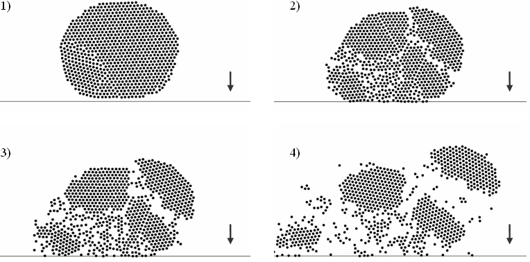
Fig. 5: Four phases of impact for the pseudo-particle model
Conclusions
The paper was focused on the numerical simulation of the fracture of a quasi-brittle ball-shaped specimen due to its impact onto a fixed solid elastic plate. The dynamic analysis was performed as 2D problem, the specimen volume was modelled in two ways: via physical discrete elements and pseudo-particles. The fragmentation due to fracture was observed within the simulations after the specimen impacted the rigid plate.
The numerical simulations using the physical discrete element model shows that the distribution of fragments of specimens remaining after the failure process follows the power law, which indicates the ability of the numerical model to identify the fractal nature of the fracture.
It was also pointed out that the second used model discretizing the specimens’ volume into pseudo-particles, in contrast to the physical discrete element model, can predict the kinematical behaviour of the fragments, into which the specimen’s body is divided after the impact, fairly well.
This feature can be attributed to the type and abilities of the interaction between the mass points within this model.
Conclusions of the presented numerical study are going to be refined and verified by further simulations with larger number of specimen representations of the model in both used variants. Three dimensional versions of the analyses lie also among considered outlooks for the future.
Acknowledgements
This outcome has been achieved with the financial support of the Czech Science Foundation – GACR, project No. 103/07/1276, and the Ministry of Education, Youth and Sports, project No. 1M0579 (CIDEAS research centre).
References
Bažant, Z.P. (1995) Scaling of Quasi-Brittle Fracture and the Fractal Question, Journal of Engineering Materials and Technology, 117, 361–367.
Bažant, Z.P. & Planas, J. (1998) Fracture and Size Effect in Concrete and other Quasibrittle Materials, CRC Press, Boca Raton, Florida.
Brandt, A. M., Prokopski, G. (1993) On the fractal dimension of fracture surfaces of concrete elements, Journal of Material Science, 28, 4762–4766.
Buchanan, M. (2000) Ubiquity: The Science of History… or Why the World is Simpler Than We Think, Weidenfeld & Nicolson, London.
Carpinteri, A., Chiaia, B., Invernizzi, S. (1999) Three-dimensional fractal analysis of concrete fracture at the meso-level, Theoretical and Applied Fracture Mechanics, 31, 163–172.
Carpinteri, A., Invernizzi, S. (2001) Uniaxial tensile test and fractal evaluation of softening damage in concrete, Fracture Mechanics of Concrete Structures, de Borst et al. (eds), Swets & Zeitlinger, Lisse, 19–25.
Frantík, P. (2007) FyDiK application, http://www.kitnarf.cz/fydik, 2007–2008.
Karihaloo, B.L. (1995) Fracture mechanics of concrete, Longman Scientific & Technical, New York.
Mandelbrot, B.B. (1982) Fractal Geometry of Nature, W. H. Freeman & Co, San Francisco.
Mechtcherine, V., Muller, H.S. (2001) Fractological investigation on the fracture in concrete, Fracture Mechanics of Concrete Structures, de Borst et al. (eds), Swets & Zeitlinger, Lisse, 81–88.
Oddershede, L., Dimon, P., Bohr, J. (1993) Self-organized criticality in fragmenting, Phys. Rev. Lett. 71, 3107–3110.
Saouma, V. E., Barton, C.C., Gamaleldin, N.A. (1990) Fractal characterization of fracture surfaces in concrete, Engineering Fracture Mechanics, 35, No. 1/2/3, 47–53.
Shah, S.P., Swartz, S.E., Ouyang, Ch. (1995) Fracture mechanics of structural concrete: applications of fracture mechanics to concrete, rock, and other quasi-brittle materials, John Wiley & Sons, Inc., New York.
van Mier, J.G.M. (1997) Fracture processes of concrete – assessment of material parameters for fracture models, CRC Press, Boca Raton, Florida.