
* Ing. Petr Frantík, Ph.D.: Faculty of Civil Engineering, Brno University of Technology, Veveří 331/95, 602 00 Brno; tel.: +420 54114 7376; e-mail: kitnarf at centrum dot cz
Summary: The paper is focused on the results of the numerical simulation of crack propagation during a three-point bending test. An effective method is used which is based on physical discretisation of the specimen, similar to non-traditional computational methods such as lattice models or particle models.
1. Introduction
Fracture experiments are a common way of obtaining material properties which are necessary for quantification of the safety and reliability of a structure. The three-point bending test (3PB) of centrally notched beams is often used for this purpose, see Fig. 1. The beam is loaded by controlled vertical displacement of the midspan point on the top of the specimen. Time series are measured of the action force of the loading machine and the midspan point displacement of the beam. The reason for the displacement-controlled loading is the requirement of recording the descending part of the load-deflection diagram.
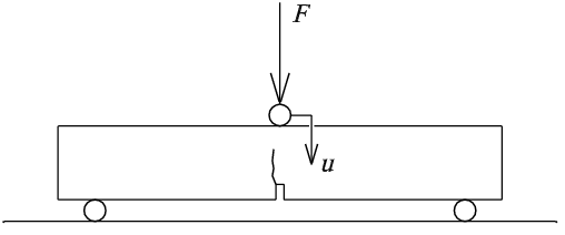
Fig. 1: Three-point bending test on a centrally notched beam
An effective method is used which is based on physical discretisation of the specimen, similar to non-traditional computational methods such as lattice models or particle models. The goal of using this method is mainly to gain qualitative agreement between real experiments and numerical solutions, together with a fast solution (via real-time simulation on a typical personal computer). This approach originates from nonlinear dynamical systems theory, according to its qualitative criteria and the principle of searching for a minimal degree-of-freedom system (Arnold 1983).
2. Method
The discrete model of the specimen is composed from mass points. The points contain the concentrated mass of the specimen. These points interact among themselves via some type of fictive force interaction. This interaction is defined in accordance with two subjects: the physical properties of the specimen material and the concept of mass point locations. For the modeling of concrete an interaction function with two linear parts and one zero part is used, where the symbol u represents the displacement between mass points, see fig. 2.
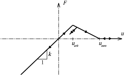
Fig. 2: Interaction function between mass points
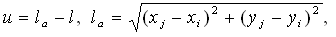
The first linear part corresponds with linear behavior and has a critical point. After this point the second linear part continues descending to zero value – the third part. In the descending part an unloading branch is used parallel to the linear part. Displacement u is calculated from the following relationship:
 | (1) |
where xi, yi are mass point coordinates, vxi, vyi are mass point velocities and l is the original distance between the mass points. The numerical model is then formulated using Newtonian classical mechanics as a nonlinear dynamical system – a system of ordinary differential equations:
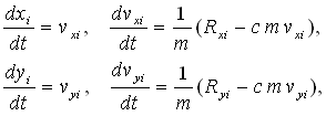 | (2) |
where m is the weight of mass point, c is the damping coefficient, t is the time and Rxi, Ryi are components of the resultant of force interactions. This equation system is solved by basic numerical methods (Euler methods, Runge-Kutta methods).
3. Dynamic behavior of the model
Two parametric tests were used for model validation: a test of the influence of the speed of displacement-controlled loading on the load-deflection diagram, and a test of the influence of loading force size on beam behavior. The model is symmetrical except for the position of the notch and contains 346 mass points in 11 layers, as well as 954 interaction springs. The specimen has height h = 0.23 L (fraction 3/13), where L is the beam span. This span L is approximately 0.87 (fraction 26/30) of the total beam length, see fig. 4. The length of the notch is approximately 0.1 h (fraction 1/11). Described interaction function is used with uzero = 10 ucrit.
Load-deflection diagrams
The first test is focused on displacement-controlled loading in order to obtain load-deflection diagrams. In fig. 3 it is possible to see a comparison of diagrams obtained from the model for different loading speeds v. The figure shows the monotonous dependency of the maximal loading force and work of fracture on the loading speed. The reason for such a dependency is the absence of time for the distribution of stress between mass points.
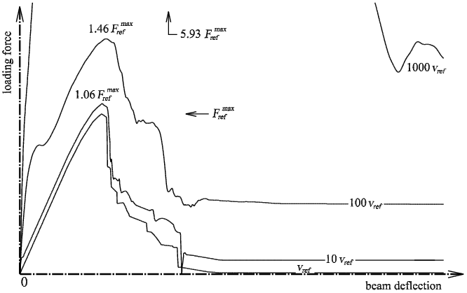
Fig. 3: Load-deflection diagrams for different loading speeds v
Note that the model has only 11 layers of mass points, and therefore the load-deflection diagrams cannot be sufficiently smooth. The reference load-deflection diagram (signed as ref) is approximately quasi-static and has at least 5 typical losses of loading stability due to the high stiffness of the notched beam (it is possible to see these as vertical lines in the diagrams).
Loading by force
The second test involved loading by force in the middle of the beam. A full-size force is placed upon an undamaged and un-deformed beam, and the simulation is started. On Fig. 4 it is possible to see classes of characteristic patterns of simulated crack propagation depending on the size of the loading force. There are two reference values: force  , corresponding to the maximal force from quasi-static loading, see fig. 3, and force Fcrack, which is the determined critical force that corresponds with the origin of the crack in dynamic simulation).
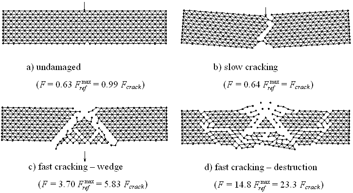
Fig. 4: Four classes of dynamic behavior of a specimen loaded by force F
There are three nontrivial classes: slow cracking similar to typical quasi-static loading by force, fast cracking with the clear formation of a shear wedge, and fast cracking with the total destruction of the specimen. Note that critical force Fcrack is lower than because a role is played by the known high influence of dynamic effects on crack initiation.
4. Conclusions
The results of the dynamic simulation of crack propagation in a three-point bended beam were presented here. These results were gained by described effective method based on physical discretisation of a specimen. Two parametric tests were performed: displacement-controlled loading with the purpose of obtaining load deflection diagrams with varying speeds, and loading by parametric force. Crack propagation in the model and load-deflection diagrams appear to be similar to the results of real experiments. From the loading by parametric force four different classes of dynamic behavior of the specimen were discovered. Future work will be focused on comparisons with particular experiments for the determination of model applicability.
Acknowledgement
This outcome has been achieved with the financial support of the Ministry of Education, Youth and Sports of the Czech Republic, project No. 1M0579, within the activities of the CIDEAS research centre.
References
Arnold, V. I. (1983) Teória katastrof (Catastrophe theory, in Russian, Moscow State University Press, 1983, 80 p), vydavateľstvo Alfa, Bratislava