
Summary: A hypothesis regarding the dynamical process of stability loss of the high and ideally symmetrical von Mises truss in a state of unsymmetrical stress is verified by the simulation of a discrete nonlinear dynamical system. The unsymmetrical stress means the von Mises truss can possibly gain an unsymmetrical post-critical shape.
Keywords: numerical simulation, beam buckling, stability, von Mises truss, nonlinear dynamical system
1 Introduction
At the present time, researchers can meet with performing of calculations of highly complex nonlinear models. Even though the complexity of nonlinear systems is largely known, the detailed analysis of the solutions found is frequently neglected due to practical reasons. One general attribute of nonlinear systems is for example the possible presence of more stable static states which are connected with the presence of unstable static states. Recognition of the correctness and stability of the solution found is not always a simple problem for the static solving method.
Fortunately, according to nonlinear systems theory, the complexity of the behaviour of nonlinear systems can be demonstrated on simple models, thanks to so-called generic attributes. The von Mises truss is one of these models, see [1]. Its analysis can exhibit generic attributes which are important for analyses of certain nonlinear systems and of other truss structures. The von Mises truss is a simple beam structure shown in Fig. 1 along with descriptive symbols used.

Figure 1: Von Mises truss
Consider a high and ideally symmetrical von Mises truss with two very slender beams of elastic material. There are many possible static states which could be obtained by the deflection/buckling of the beams. The existence of these states was described in detail in [2], where the occurrence of two kinds of von Mises truss post-critical interaction was demonstrated: symmetrical and unsymmetrical stress, see Fig. 2.
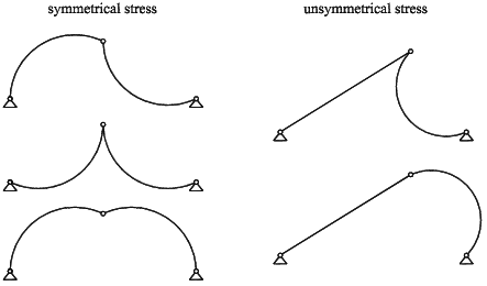
Figure 2: Possible post-critical states of the truss without symmetrical partners
Symmetrical stress of the von Mises truss is a static state which exists for every value of the ratio h/L, where h is the height of the von Mises truss and L is the length of its beams, during which h < L. However, unsymmetrical stress exists for some values of the ratio h/L only. The minimal height h of the von Mises truss with the presence of unsymmetrical stress was computed as hmin = 0.5774L without taking into account normal strain on the beams (it was assumed that the beams were very slender), see [2]. Moreover, the presence of unsymmetrical stress is generally limited by the position of the middle hinge, see Fig. 3 for von Mises truss
h = 0.8L.

Figure 3: Dependency of the force F applied to the middle hinge on the vertical displacement w for von Mises truss h = 0.8L (Fcr is the critical force of the von Mises truss, i.e. the force necessary for the von Mises truss to lose stability)
The dependency of the force F on the middle hinge position (specified by vertical displacement w, see Fig. 1) for the von Mises truss h = 0.8L, taken from [2], is shown on Fig. 3. The diagram shows the end of unsymmetrical stress after achieving a displacement of approximately wmax = 0.637h.
2 Task
As mentioned in the introduction, we shall concentrate on the process of von Mises truss deflection. For the purpose of simplification we will investigate a von Mises truss where h = 0.8L only, and loading will take the form of increments of vertical displacement of the middle hinge (it is a post-critical task). A special numerical model was created for this purpose, see Fig. 4.

Figure 4: Scheme of a discrete numerical model of a von Mises truss
The beams of a von Mises truss are divided into a specific number of elements with the same length. Every element has an inner spring (which allows normal elongation of the beam). The elements are connected together by hinges with rotational springs. Both types of springs are considered to be linear:
| (1) |
where Fl is the internal force in normal spring, Mf is the internal moment in rotational spring, kl is the stiffness of the normal spring, kf is the stiffness of the rotational spring, dl is the elongation of the normal spring (elongation of the element), and d is the angular displacement of the rotational spring (angular displacement between connected elements).
The potential energy Ep which is accumulated within these springs can be written in the following form:
 | (2) |
where nl is the number of normal springs, nf is the number of rotational springs.
The deformation state of the described von Mises truss model is exactly given by the positions of each hinge (it is true if |di | <  ). The position is specified by the coordinates (xi, yi), where i is the index of the hinge. For elongation of the normal springs the following applies:
 | (3) |
where l is original length of the element (element without stress) and li is the length of the element after displacement. For the angular displacement of the rotational springs the following applies:
 | (4) |
where i is the angular displacement of element i (the element between rotational springs i and i + 1). The equations (3) and (4) are geometrically exact formulations of the model.
3 Potential energy surface
The described model can be used to investigate the structure of the potential energy surface of the truss, from which information the deformational behaviour of the von Mises truss can be determined. The drawing of the potential energy surface took place according to the procedure published in the paper [3]. This procedure is based on a search for extreme values of potential energy Ep(equation (2)) using the Newton iterative method:
1. First we place the von Mises truss in a stable static state discovered, for example, via using the Newton iterative method. Then we fix the position of the middle hinge.
2. The next step is the ''small'' shift in the position of the fixed middle hinge, and the finding of the new extreme value for potential energy using the Newton iterative method.
3. Point two can be repeated as long as is necessary to obtain the position at which we want to know the value of potential energy. This is followed by the analysis of the state gained, and the recording of the potential energy value.
The energetic surface obtained by this procedure is shown with the help of transformation in Fig. 5. The surface is transformed into a dimensionless form due to practical reasons so that the potential energy symmetrical stress (e.g. the middle hinge undergoes vertical displacement only; it is the vertical line x = 0.6 m in Fig. 5) has a value of 1.00. The contours were obtained from the grid of the computed values of potential energy by the programme Gnuplot [4].

Figure 5: The transformed potential energy surface of the von Mises truss, illustrated by contours, shown in the plane of the possible positions of the middle hinge.
Unsymmetrical stress is recognizable in Fig. 5 as a ''basin'' at the left and right edges of the surface (highlighted by bold line). It can therefore be deduced that unsymmetrical stress is a stable static state throughout the whole period of its existence (see Fig. 3) if the von Mises truss is loaded by vertical displacement of the fixed middle hinge. On the other hand, symmetrical stress represented by a vertical line is in this sense a stable static state in the interval wstab  (0.48, h),
e.g. ystab (0, 0.32) only (highlighted by solid line), see Fig. 5. In the ''upper'' part symmetrical stress is an unstable static state (vertical dashed line). From the surface shown it is possible to see the existence of the next unstable static state highlighted by dashed curve, see Fig. 5. The deformed shape of the von Mises truss when achieving this state is shown in Fig. 6. Its existence indicates that symmetrical and unsymmetrical stresses are stable static states simultaneously with this newly found unstable state.

Figure 6: Newly found unstable static state with a small area of existence.
From the potential energy surface of the von Mises truss h = 0.8L on Fig. 5 the following process of deflection can be deduced: If the von Mises truss is in an initial unstressed state, then a small vertical displacement of the middle hinge causes buckling into symmetrical stress, which will transform into unsymmetrical stress due to the asymmetry of the initial conditions of arbitrary origin. Along the next displacement the von Mises truss will remain in a state of unsymmetrical stress until the end of the existence of unsymmetrical stress is achieved (e.g. at a displacement of w = 0.64h, or at coordinates y = 0.29 m). Overstepping of this point is followed by the fall of unsymmetrical stress into symmetrical stress. Finally, the von Mises truss will remain in a state of symmetrical stress until displacement w = h, or to the coordinates y = 0.0 m.
4 A dynamical solution
In order to confirm the above-mentioned hypothesis regarding the course of deformation of a von Mises truss, the given model was formulated as a nonlinear dynamical system. For the sake of simplicity we can assume the concentration of the mass of the beam in hinges. Due to this assumption, equations of motion can be derived using the Newton's law in the following form:
 | (5) |
where c is the damping coeffcient, m is the mass of the hinge, vxi, vyi are the velocity vector components of the hinges and Rxi, Ryi are the vector components of the resultant force Ri by which the springs act on the hinge. The resultant Ri = f(Fl, Mf), see eq. (1), is the only nonlinear component featured in equations of motion (5) due to nonlinearity in relation (3) and (4).
The confirmation by dynamical solution was carried out in the following way: First, two beams were created (each one consisting of 8 elements) lying on the axis x, connected by a middle hinge and supported by the hinge fixed supports on their boundaries. The next step was the fixation of the middle hinge against the direction of free vertical displacement (the hinge is on coordinates (1.0, 0.0), see the coordination system in Fig. 4). Then, the right hinge support was moved in small steps from the initial position x = 2.0 m to the position x = 1.2 m, whereby the von Mises truss appears in a postcritical form. The last phase of the simulation was the slow moving of the middle hinge (fixed in the vertical direction) up to the coordinates y = 0.8 m and back down to the coordinates y = 0.0 m. The results of the simulation are shown on Fig. 7 in the potential energy surface of the von Mises truss.

Figure 7: The transformed potential energy surface of the von Mises truss with the trajectory of the middle hinge in the dynamical simulation (marked as a bold line with arrows indicating the direction of movement).
5 Conclusions
Presented in this paper was confirmation of the hypothesis regarding the dynamical process of stability loss experienced by high and ideally symmetrical von Mises trusses in the state of unsymmetrical stress brought on in dynamical simulations. The hypothesis was confirmed by the simulation, during which it was shown that the methods of analysis of potential energy are certainly well applied and allow the creation of a clear picture of the characteristics of a simple non-linear system.
The observed properties of von Mises truss are important for recognition of generic attributes of certain nonlinear systems and of other truss structures. Presented solution can be used for theoretical analysis of similar problems in technical practice.
A new post-critical solution of the von Mises truss was presented here. The catastrophe theory can also be used for these purposes, see [5]. The author is interested in this method and expects its application to occur in the future.
Java applet of the von Mises truss simulation is available on Internet web page [6]. Using this applet it is possible to manually repeat the described process of the von Mises truss deflection.
6 Acknowledgement
The paper was written under grant No. MSMT 52130/2005 according to a decision regarding the proposal for research project MSM0021630504.
References
[1] Bažant Z. P., Cedolin L.: Stability of Structures, Oxford University Press, Oxford, 1991.
[2] Frantík P.: Rozbor existence řešení dokonalého symetrického vzpěradla, sborník mezinárodní konference Modelování v mechanice, VŠB-TU Ostrava, 2004, pp. 43-48.
[3] Frantík P.: Stability Study of the Elastic Loop, proc. 5th International Ph.D. Symposium in Civil Engineering, vol. II, TU Delft, Netherlands, 2004, pp. 1083-1088.
[4] Williams T., Kelley C.: \& others GNUPLOT ver. 4.0., 2004, http://www.gnuplot.info/.
[5] Arnold V. I., Afrajmovich V. S., Il`Yashenko YU. S., Shilnikov L. P.: Bifurcation Theory and Catastrophe Theory, Springer-Verlag, New York, 1999.
[6] Frantík P.: Slender von Mises truss, 2005, http://www.fce.vutbr.cz/STM/frantik.p/applets/dynmis/simul.htm.